Written by Manika Garg, Sustainability Consultant, Love Design Studio
When we talk about creating resilient and thermally efficient buildings, the conversation often centres on visible interventions: better windows, thicker insulation, solar panels, heat pumps and external shading. These measures are important, but they are only part of the story.
Heat doesn't just move through walls and glazing. It also finds its way through the junctions, corners and connections that hold a building together. These weak points, known as thermal bridges, can significantly affect energy use, occupant comfort and building durability. Yet despite their impact, they rarely receive the same attention as other aspects of building design.
The importance of getting these details right has become more apparent in light of recent policy developments. In particular, Awaab’s Law* – introduced in response to serious housing health failures – has brought new attention to the risks associated with damp and mould in residential buildings. Poorly designed junctions can create cold surfaces where condensation forms, increasing the likelihood of mould growth. As a result, thermal bridging is no longer simply a matter of technical detailing or energy performance, it is now recognised as a key consideration for occupant health, building resilience and regulatory compliance.
What is thermal bridging
Thermal bridging happens when heat takes an easier path through a building than it should. Instead of moving slowly through well‑insulated areas, heat finds a shortcut through materials that conduct it more easily, such as steel, concrete or areas where insulation is missing or reduced.
The Building Research Establishment (BRE) defines thermal bridging as “[…] occurring when an area of a building has significantly higher heat transfer than the surrounding parts. Breaks in insulation, reduced insulation or more conductive materials can contribute to thermal bridge effects.”
Linear thermal bridges (Psi values)
In this article, we will discuss the heat flow that occurs at linear junctions (such as wall‑to‑floor, wall‑to‑roof or wall‑to‑window connections), also known as linear thermal transmittance, denoted by Psi value (ψ).
· A Psi value represents the amount of heat lost per metre of junction
· Lower Psi values indicate better‑performing junctions
While U‑values describe heat loss through surfaces, Psi values describe heat loss along edges and junctions, the places where materials meet and heat can escape more easily.
Why high-performance buildings can still lose heat
New builds and retrofits often achieve very high levels of insulation. For example, wall, floor and roof U-values (a measure of how much heat passes through a building element – lower value means better insulation) can now be in the range of 0.10–0.14 W/m²K.
When this is combined with improved airtightness (below 3 m³/hr·m² at 50Pa) and mechanical ventilation with heat recovery (MVHR), which recovers heat from outgoing air, we would expect to see excellent energy performance results. As the building fabric becomes more efficient, the relative impact of thermal bridges becomes increasingly significant.
Not just a winter problem
Thermal bridging is most commonly discussed in the context of winter heat loss, where heat escapes through poorly insulated junctions and increases heating demand. As summers become hotter and heatwaves more frequent, the importance of an efficient building envelope is becoming more apparent. With many more buildings in the UK likely to require active cooling in the future, attention should be given not only to reducing heat loss in winter but also to maintaining comfortable indoor conditions during extreme summer heat. As external temperatures in the UK could approach or exceed 40°C, poorly designed junctions may reduce the effectiveness of cooling strategies, highlighting the need for careful thermal envelope design as part of climate resilient design.
Let’s look at lintel junctions
To understand what really happens at a junction, let’s take a closer look at a common example: a lintel. A lintel is the structural beam placed above openings to transfer load away from windows and doors. Typically, lintels are made from materials such as steel or concrete and sit within the junction between a wall and an opening.
For comparison, we have taken three different types of lintels within the same wall build-up (a 400mm fully filled masonry wall). In this example, the wall is tested with three different junction conditions: a steel lintel with a cavity tray, a perforated steel lintel, and a concrete lintel.
As shown in the image below, each option supports the same wall construction, but the way the heat moves through the junction changes significantly depending on the material used.
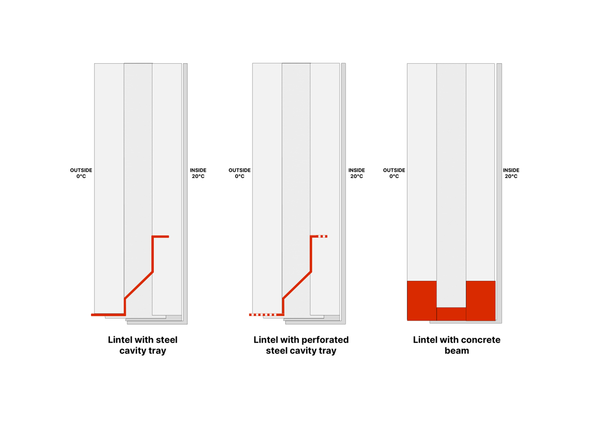
Figure 1: The three sections above show a wall built up with fully filled cavity supported by three different types of lintels.
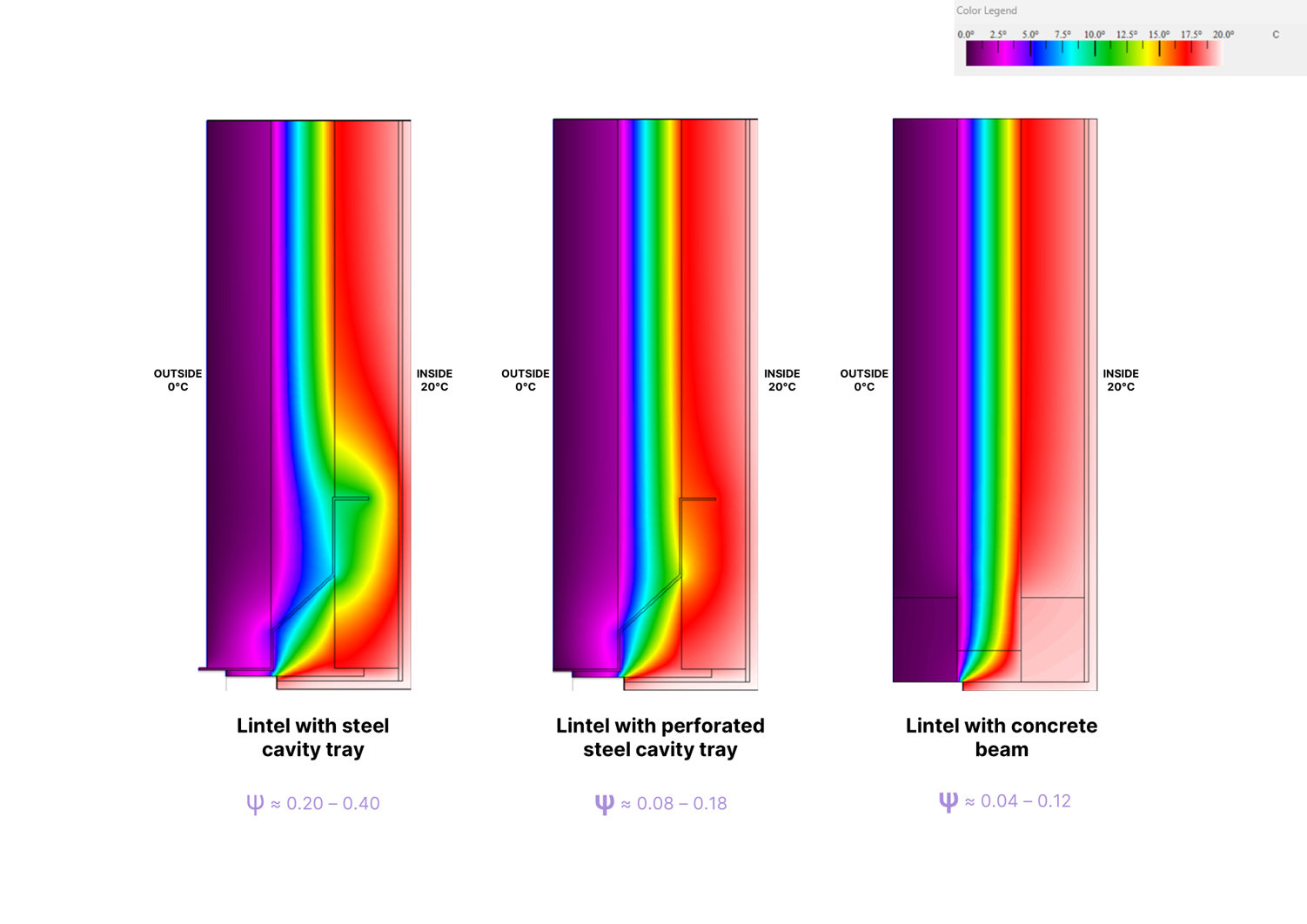
Figure 2: Illustration depicts the flow of heat that happens when the same wall-built ups with different junctions are subjected to same inside and outside environment.
How heat behaves at these junctions
Away from the junction, the wall performs consistently across all three examples, as shown in the diagram above. The internal temperature at the inner leaf is very close to the inside temperature, which is about 17–20°C. The external leaf of the wall has a very low temperature of around 0–2°C. The insulation layer in the cavity effectively slows heat transfer through the wall, maintaining a clear thermal divide between inside and outside.
However, this behaviour changes significantly at the junction.
Steel lintel
In the case of the steel lintel, the heat is transferred much faster. Steel is highly conductive, meaning it provides an easy path for heat to flow from the warm internal environment to the colder external environment. This results in heat being drawn through the junction more easily, increasing heat loss.
Perforated steel lintel
With the perforated steel lintel, the same material is used, but the introduction of perforations disrupts the continuous path of heat flow. These interruptions increase thermal resistance, reducing the overall rate of heat transfer compared to a solid steel lintel. This results in improved thermal performance, although the element is still relatively conductive.
Concrete lintel
In the case of the concrete lintel, the junction performs better than the wall itself. Concrete has much lower thermal conductivity than steel and the masonry wall, meaning it slows heat transfer more effectively. In this scenario, the junction can perform better thermally than the surrounding masonry wall, due to the relative material properties involved.
While the concrete lintel offers the best thermal performance of the three options, relying on concrete can restrict future flexibility and increase embodied carbon. A solution such as the perforated steel lintel can provide a good middle ground, improving operational performance and lowering embodied carbon. This type of thinking aligns well with Greater London Authority (GLA) policy and future-proofed design thinking.
Policy and risk
Beyond thermal performance alone, junction design is now directly linked to issues of health, compliance, and regulatory risk. With the introduction of Awaab’s Law, housing providers are under increasing obligation to address conditions that can lead to damp and mould. This places greater scrutiny on how buildings manage moisture risk – and thermal bridges are a key part of this.
Poorly resolved junctions can lead to moisture and condensation build-up around junctions, causing damp and mould hazards. With tightening EPC scrutiny, thermal bridging can no longer rely on assumed Accredited Construction Details or default ψ-values. Accurate modelling directly influences SAP calculations (Standard Assessment Procedure – the UK government’s official method for assessing the energy performance of new homes) and therefore EPC outcomes. When junctions are poorly assessed, the performance gap between design and operation widens. What appears efficient in assessment may underperform in use.
A warm and healthy house is not a want or desire – it is a fundamental need. Achieving it depends on how carefully we design and resolve the details, especially at junctions where most of the hidden heat loss occurs. This is not about chasing certifications, it is about delivering buildings that genuinely perform well in use.
*This law is named in memory of 2-year-old Awaab Ishak, who died in 2020 as a result of a severe respiratory condition due to prolonged exposure to mould in his home.